Heating solids – contact heating
Information required to determine the wattage of the heating elements for heating of solid materials:
- Specification of heated material including the surface (glossy, black, etc.).
- Weight, shape, and location of material.
- Starting and target temperature.
- Time required for heating.
- Information about the ambient temperature and the method of insulation.
For the design of a specific solution, i.e. selection of the type of heating element, shape, and dimension, it is necessary to define:
- The dimensions and the shape of the heated part, the place, and the space designated for electric termination (leads).
- Environment and limiting factors in the place of electric termination (e.g. vibrations, movement of parts, humidity, bending of leads in the place of the leads of the part, risk of mechanical damage or contamination by oil or other liquids, explosive character of the environment, etc.)
- Proposed method of temperature regulation.
For more information or help to resolve specific heating issues, please contact us.
What type of heater do you need?
Heating cartridges
High-performance cartridge heaters – if the shape and the size of heated part allows, they are very useful and effective method of heating. Improper due to wide parts – for more information, see “High-performance cartridge heaters”
Medium-performance cartridge heaters – Maximum recommended working temperatures and the watt density are lower than high-performance cartridge heaters. Logical option for wider demanding applications where high-performance cartridge heaters cannot be used. – for more information, see “Medium-performance cartridge heaters“
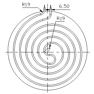
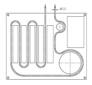
ø 6.5 mm cartridge heaters are a suitable solution for when it is necessary to insert the rod into a groove-shaped on the surface of the heated metal part. The groove is produced wider by 0.1 – 1.5 mm than the heating rod according to the method of mounting, the working temperature of the part, the shape of the element, and the watt density of the heating rod.
If the client also ensures shaping of heating cartridges with the diameter of 6.5 mm into the groove, the minimum recommended diameter of bending is 38 mm (N.B. once shaped, the rod must not be straightened back). After shaping or pressing the heating elements into the groove, it must be retested for electric strength and the electric circuit according to (ČSN EN 60335-1).
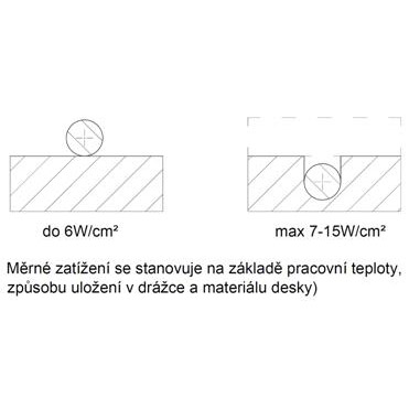
The recommended watt density of the rods is 7-15 W/cm2, according to the method of the placement of the rods in the groove of the heated material, the working temperatures, and the material of the heated part. The maximum recommended working temperature is stated on the basis of the watt density of the rods, the method of the placement of rods in the groove, and material of the board.
Low-performance cartridge heaters – logical option for less heat exposed or wider applications. For details, see “Low-performance cartridge heaters”.
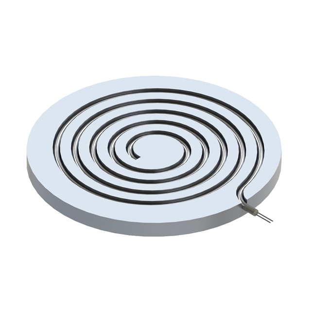
Tubular heating elements
In many cases, this is the most affordable and a more variable solution in terms of shape than heating cartridges.
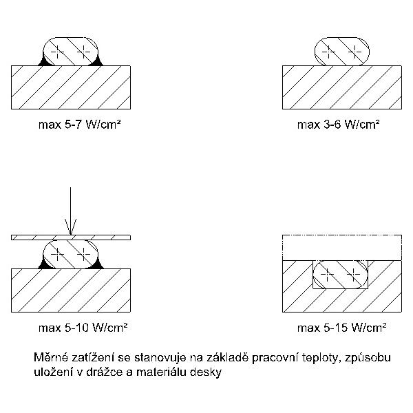
Methods of contact heating by tubular heating rods:
The groove is produced wider by 0.1 – 1.5 mm than the heating rod according to the method of mounting, the working temperature of the part, the shape of the element, and the watt density of the heating rod.
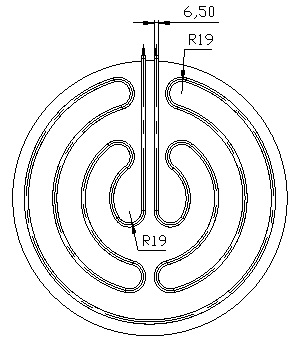
ø 6.5 mm and ø 8.5 mm rods are used (for more complicated shapes, rods with ø 6.5 mm). If the heating elements are designated into the groove, this information must be provided. If the client ensures shaping of heating rods into the groove, then for rods with ø 6.5 mm, the minimum recommended diameter of bending is 38 mm. N.B. Once shaped, the rod must not be straightened back. If elements are shaped or pressed into the groove, they must be retested for electric strength and the electrical circuit according to (ČSN EN 60335-1).
The maximum recommended working temperature of the rods is stated on the basis of watt density W/cm2, the method of placing the rods in the groove, and the material for the plate.
The other method used in industrial applications is casting the shaped tubular heating rods into aluminium alloy (we do not do this in our company although it can be arranged).
For details, see “Tubular heating elements”.
Flat tubular heating elements
Often the most affordable solution compared with cartridges. Recommended for applications where outlets on one side of the rod are required.
Methods of contact heating by flat tubular heating rods:
For details, see “Flat tubular heating elements”.
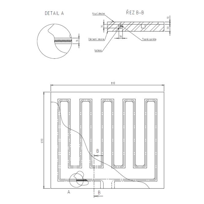
Flat heating rods are, as a standard, located in the linear grooves of the rectangular profile. The maximum recommended working temperature is stated on the basis of the watt density of rod W/cm2, the method of placing the rods in the groove and the material for the board.
Heating wire inserted directly into the heated metal board.
This is often a suitable alternative for heating metal boards with large dimensions. Long service life Usable only for applications without the risk of contamination of insulation.
Heating strips and mica plate heaters
Contact heating of solid materials is characterised by the method of use. For details, see “Band heaters, Mica plate heaters”.
Sheath materials
- Brass – up to 400°C
- Copper – up to 165 °C
- AISI 321 – up to 750 °C
- AISI 304 – up to 650 °C
- AISI 309 – resistance of the tube (non-heating rod) up to 950 °C
- INCOLOY 800 – resistance of the tube (non-heating rod) up to 1,050 °C
- Aluminium – up to 400 °C
Regulation of temperature hints for heating solids
(Also applies to other types of heating although in the case of contact heating of solid materials, i.e. conduction, where there is the common use of higher working temperatures together with the requirement for the relatively exact regulation of working temperatures. Due to these reasons, the correct method of regulation has a more important impact on the service life of the heating elements than in the case of heating liquids or gases).
Connection and disconnection within the range 40s- 60s causes repeated full disconnection and shrinking of the resistance wire. This results in high stressing and oxidation of the heating wire inside the heating rod. Capillary and bimetallic thermostats have too high connection / disconnection difference.
For the purpose of increasing the service life of the heating rods, it is recommended to use electronic regulation (ON/OFF regulator or PID regulator) together with a mechanical relay where the switching times must be under 10s. The ideal solution is regulation with the controlled electric voltage in time intervals up to 1s i.e. thermal regulation + SSR (solid-state relay) or SCR relay.
The thermal sensor is located a maximum of 10 mm from the heating rods.